Zewail City Modification for Filament Based Memristor Models
In our work [1], different memristor models have been compared in multi-bit transient analysis. Moreover, Zewail city modified model has been proposed to overcome the limitations of existing models. The different models are fitted to the experimental data of IMEC HfOx-based memristor [2-4]. For simulation, Verilog-A models [5-7] are simulated on Cadence virtuoso with TSMC 130 nm technology file. The fitting parameters used are reported in Table I. As shown in Fig (1), A 2V sinusoidal signal at 5Hz is used for computing the IV characteristics of the models, the transistor used has a minimum length of 130 nm, a width of 155 nm, and a gate voltage of 0.44V limiting the compliance current to 10 μA.
TABLE I: FITTING PARAMETERS FOR DIFFERENT MEMRISTOR MODELS |
||||
| Simmons Tunneling Barrier Model [8] | VTEAM Model [9] | Stanford Model [10,11] | Arizona State University Model (ASU) [12] | Zewail City Model (ZC) [1] |
| D = 3.5 nm | D = 3.5 nm | g0 = 0.6 nm | g0 = 0.6 nm | g0 = 6e-10 m |
| Roff = 1.25 M𝛺 | Roff = 1.25 M𝛺 | V0= 5.5 V | V0= 5.5 V | V0= 5.5 V |
| Ron = 86.6 K𝛺 | Ron = 86.6 K𝛺 | ν = 5e7 m/S | ν = 1000 m/S | ν = 1000 m/S |
| Coff = 3 pm/S | Koff = -2.5 m/S | I0 = 75 mA | I0 = 75 mA | I0 = 7 e-5 A |
| Con = 2 pm/S | Kon= 20 mm/S | Ea = 1.5 eV | Eag = 1.54 eV
Ear = 1.475 eV |
Eag = 1.475 eV
Ear = 1.475 eV |
| Ioff = -55 nA | Voff = 1.31 V | a0 = 0.25 nm | a0 = 0.25 nm | a0 = 2.5e-10 m |
| Ion = -17 nA | Von = -0.54 V | Gapmin = 0.1 nm | Gapmin = 0.1 nm | Gapmin = 1e-10 m |
| Xc =1.2 nm | αoff = 3 | Gapmax = 1.7 nm | Gapmax = 1.7 nm | Gapmax = 17e-10 m |
| b = 1 mA | αon = 12 | Tox = 5 nm | L = 5 nm | L = 5e-9 m |
| aon = 9 nm | _________ | b = 1.4 | b = 1.55 | b = 1.55 |
| aoff = 1 pm | _________ | ϒ0 = 21 | ϒ0 = 21 | ϒ0 = 21 |
| _________ | _________ | RTh = 500×103 K/Watt | CTh = 3.18×10⁻¹⁶ J/K | CTh = 3.18×10⁻¹⁶ J/K |
| _________ | _________ | _________ | 𝜏Th =230 pS | 𝜏Th =230 pS |
| _________ | _________ | _________ | _________ | n = 750 |
| _________ | _________ | _________ | _________ | m = 750 |
In order to use these parameters, you are requested to cite [1].
For understanding the physical or mathematical interpretation of the given parameters, it is advised to refer for the original papers proposing these models: Simmons Tunnel Barrier Model [8], the Voltage ThrEshold Adaptive Memristor model (VTEAM) [9], the Stanford model [10, 11], and Arizona State University (ASU) modification for Stanford model [12].

Fig. 1. The circuit used for Fitting Memristor Models to experimental data [1-3].
The relative root mean square (RMS) error is used to evaluate the fitting of these model according to:
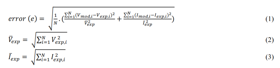
where N is the number of experimental data points, 𝑉mod ,𝑖 and 𝐼mod ,𝑖 are the corresponding voltage and current of the given model, 𝑉 exp ,𝑖 and 𝐼exp ,𝑖 are the corresponding voltage and current of the experimental data, and and are the Euclidean norms of the voltage and current of the experimental data. Calculated relative root mean square (RMS) error of fitting different models is given in Table II, the maximum fitting error is below 5%.
TABLE II: ROOT MEAN SQUARE ERROR OF FITTED MODELS
| Model | Simmons Tunnel Barrier | VTEAM | Stanford | ASU Modification | ZC Modification |
| e | 3.45% | 4.94% | 4.74% | 3.96 % | 4.83% |
References:
[1] E. R. Berikaa, A. Khalil, H. Hossam, M. El-Dessouky, and H. Mostafa, “Multi-Bit RRAM Transient Modelling and Analysis ,” IEEE 30th International Conference on Microelectronics (ICM), 2018.
[2] Y. Y. Chen, B. Govoreanu, L. Goux, R. Degraeve, A. Fantini, G. S. Kar, D. J. Wouters, G. Groeseneken, J. A. Kittl, M. Jurczak, and L. Altimime, “Balancing SET/RESET pulse for > 1010 endurance in HfO2/Hf 1T1R bipolar RRAM,” IEEE Trans. Electron Devices, vol. 59, no. 12, pp. 3243–3249, Dec. 2012. [3] Y. Y. Chen, M. Komura, R. Degraeve, B. Govoreanu, L. Goux, A. Fantini, N. Raghavan, S. Clima, L. Zhang, A. Belmonte, A. Redolfi, G. S. Kar, G. Groeseneken, D. J. Wouters, and M. Jurczak, “Improvement of data retention in HfO2/Hf 1T1R RRAM cell under low operating current,” 2013 IEEE International Electron Devices Meeting, 2013. [4] A. Fantini, L. Goux, R. Degraeve, D. Wouters, N. Raghavan, G. Kar, A. Belmonte, Y.-Y. Chen, B. Govoreanu, and M. Jurczak, “Intrinsic switching variability in HfO2 RRAM,” 2013 5th IEEE International Memory Workshop, 2013. [5] Verilog-A for Memristor Models. [Online]. Available: https://asic2.group/wp-content/uploads/2017/06/VerilogA-models-technical-report.pdf [6] Z. Jiang, Wong, and H.-S. P. Wong. Stanford University Resistive-Switching Random Access Memory (RRAM) Verilog-A Model. nanoHUB. doi:10.4231/D37H1DN48, 2014. [7] ASU RRAM Model. [Online]. Available: http://faculty.engineering.asu. edu/shimengyu/model-downloads/ [8] M. D. Pickett, D. B. Strukov, J. L. Borghetti, J. J. Yang, G. S. Snider, D. R. Stewart, and R. S. Williams, “Switching dynamics in titanium dioxide memristive devices,” Journal of Applied Physics, vol. 106, no. 7, p. 074508, 2009. [9] S. Kvatinsky, M. Ramadan, E. G. Friedman, and A. Kolodny, “VTEAM: A General Model for Voltage-Controlled Memristors,” IEEE Transactions on Circuits and Systems II: Express Briefs, vol. 62, no. 8, pp. 786–790, 2015. [10] Z. Jiang, S. Yu, Y. Wu, J. H. Engel, X. Guan, and H.-S. P. Wong, “Verilog-A compact model for oxide-based resistive random access memory (RRAM),” 2014 International Conference on Simulation of Semiconductor Processes and Devices (SISPAD), 2014. [11] Z. Jiang, Y. Wu, S. Yu, L. Yang, K. Song, Z. Karim and H.-P. Wong, “A Compact Model for Metal-Oxide Resistive Random Access Memory With Experiment Verification,” IEEE Transactions on Electron Devices, vol. 63,pp. 1884-1892, 2016. [12] P.-Y. Chen and S. Yu, “Compact Modeling of RRAM Devices and Its Applications in 1T1R and 1S1R Array Design,” IEEE Transactions on Electron Devices, vol. 62, no. 12, pp. 4022–4028, 2015.
/*******************************************************************
Metal Oxide Resistive Random Access Memory Verilog-A implementation
based on
[1] E. R. Berikaa, A. Khalil, H. Hossam, M. El-Dessouky, and H. Mostafa, “Multi-Bit RRAM Transient Modelling and Analysis ,â€Â IEEE 30th International Conference on Microelectronics (ICM), 2018.
[2] P.-Y. Chen and S. Yu, “Compact Modeling of RRAM Devices and Its Applications in 1T1R and 1S1R Array Design,â€Â IEEE Transactions on Electron Devices, vol. 62, no. 12, pp. 4022–4028, 2015.
[3] Z. Jiang, S. Yu, Y. Wu, J. H. Engel, X. Guan, and H.-S. P. Wong, “Verilog-A compact model for oxide-based resistive random access memory (RRAM),â€Â 2014 International Conference on Simulation of Semiconductor Processes and Devices (SISPAD), 2014.
[4] Z. Jiang, Y. Wu, S. Yu, L. Yang, K. Song, Z. Karim and H.-P. Wong, “A Compact Model for Metal-Oxide Resistive Random Access Memory With Experiment Verification,†IEEE Transactions on Electron Devices, vol. 63,pp. 1884-1892, 2016.
*******************************************************************/
`include “constants.vams”
`include “disciplines.vams”
module Zewail_city_MM(Nt, Nb,gap_out,R_out, temp_out);
inout Nt, Nb;
output gap_out,R_out, temp_out;
electrical Nt, Nb, gap_out, R_out, temp_out;
parameter real kb = `P_K; // Boltzmann’s constant= 1.3806503e-23 (J/K)
parameter real q = `P_Q; // Electron charge= 1.6e-19 (C)
// Device parameters
parameter real L = 5e-9 from (0:inf); // Oxide thickness (m)
parameter real gap_min = 0.1e-9 from (0:L); // Min. gap distance (m)
parameter real gap_max = 1.7e-9 from (gap_min:L); // Max. gap distance (m)
parameter real gap_ini = 0.1e-9 from [gap_min:gap_max]; // Initial gap distance (m)
parameter real a0 = 0.25e-9 from (0:inf); // Atomic distance (m)
parameter real Eag = 1.5 from (0:inf); // Activation energy for vacancy generation (eV)
parameter real Ear = 1.5 from (0:inf); // Activation energy for vacancy recombination (eV)
// I-V characteristics
parameter real I0 = 6.14e-5 from (0:inf);
parameter real g0 = 2.7505e-10 from (0:inf);
parameter real V0 = 0.43 from (0:inf);
// Gap dynamics
parameter real Vel0 = 150 from (0:inf);
parameter real gamma0 = 16.5 from (0:inf);
parameter real g1 = 1e-9 from (0:inf);
parameter real beta = 1.25 from (0:gamma0/(pow(gap_max/g1,3)));
real gap; // Current gap (m)
real gap_ddt; // Gap growth velocity (m/s)
real gamma; // Local enhancement factor
// Temperature dynamics
parameter real T0 = 273+25 from (0:inf); // Ambient temperature (K)
parameter real Cth = 3.1825e-16 from (0:inf); // Effective thermal capacitance (J/K)
parameter real Tau_th = 2.3e-10 from (0:inf); // Effective thermal time constant (s)
real temperature; // Current temperature (K)
// Simulation time control
parameter real tstep = 1e-9 from (0:inf); // Max. internal timestep (s)
real c_time; // Current timestep (s)
real p_time; // Previous timestep (s)
real dt; // Difference between current and previous timestep (s)
// Resitance
parameter real Vread = 0.1; // Read voltage (V)
real Iread; // Read current @Vread (A)
// Zewail City Modification parameters
parameter real n = 750 from (1:inf);
parameter real m = 750 from (1:inf);
real integ;
real express;
// Variations
parameter integer rand_seed_ini = 0 from(-1.6e9: 1.6e9);
parameter real deltaGap0 = 0.02 from[0: 0.1);
parameter integer model_switch = 0 from[0: 1]; // 1: for variations
parameter real T_smth = 500 from(400: 600); // activation energy for vacancy generation/recombination
parameter real T_crit = 450 from(390: 460); // threshold temperature for significant random variations
integer rand_seed;
real deltaGap;
real gap_random_ddt;
analog begin
@(initial_step) begin
temperature = T0;
gap = gap_ini;
rand_seed = rand_seed_ini;
end
$bound_step(tstep); // Bound the time step
c_time = $abstime; // Get current timestep
dt = c_time-p_time;
// Calculate the local enhancement factor
gamma = gamma0 – beta*pow(gap/g1, 3);
// Gap dynamics
gap_ddt = -Vel0*( exp(-q*Eag/kb/temperature)*exp(gamma*a0/L*q*V(Nt,Nb)/kb/temperature) – exp(-q*Ear/kb/temperature)*exp(-gamma*a0/L*q*V(Nt,Nb)/kb/temperature) );
deltaGap = deltaGap0 * model_switch;
gap_random_ddt = $rdist_normal(rand_seed, 0, 1) * deltaGap / (1 + exp((T_crit – temperature)/T_smth));
// Butterworth window function
if(gap_ddt > 0) begin
express = gap/gap_max;
integ = (1/sqrt(1+pow(express,n)))*(gap_ddt+gap_random_ddt)*dt;
end
else begin
express = (L + gap_min – gap)/L;
integ = (1/sqrt(1+pow(express,m)))*(gap_ddt+gap_random_ddt)*dt;
end
gap = gap + integ;
// Limitation on the gap growth
if (gap > L)
gap = L;
else if (gap < 0)
gap = 0;
// Calculate the current
I(Nt,Nb) <+ I0*exp(-gap/g0)*sinh(V(Nt,Nb)/V0);
// Calculate the local temperature (implicit form)
temperature = (temperature + dt*(abs(V(Nt,Nb)*I(Nt,Nb))/Cth+T0/Tau_th))/(1+dt/Tau_th);
// Parameter extraction
V(gap_out) <+ gap; // Gap distance
V(temp_out) <+ temperature; // Temperature
Iread = I0*exp(-gap/g0)*sinh(Vread/V0);
V(R_out) <+ Vread/Iread; // Resistance @Vread
p_time = $abstime; // Record current timestep for the previous timestep at next timestep
end
endmodule